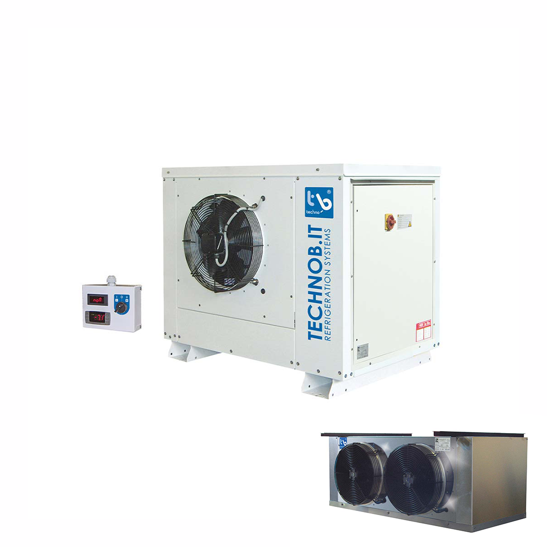
Bi-block
Bi-block BI
FEATURES
- Electronic controller with alarm module.
- Expansion type with thermostatic valve.
- All compressors are equipped with crankcase preheating resistor.
- Semi-hermetic compressors are equipped with a thermistor; a differential oil protection pressure switch is installed on models equipped with an oil pump.
- Compressors with displaced volume above 52 m3 /h are part-winding type starting.
- All units are equipped with adjustable low-pressure and high-pressure switches in accordance with the 2014/68/EU “Pressure Equipment” Directive.
- Panel equipped with pressure switches and service outlets accessible while the machine is running.
- Liquid indicator.
- Solenoid valve on the liquid line.
- All models are supplied with liquid receiver with safety valve, in accordance with the Pressure Equipment Directive 2014/68/EU.
- Liquid separator on the suction line.
- Condenser fan control pressure switch. On request, it can be replaced by the electronic variable speed drive of condenser fans.
- Remote control panel including keypad, alarm display, and 5 m long cable already connected to ‘unit (can be supplied on request with different lengths up to 20 meters).
- Direct condensate water discharge.
- Resistance in the condensate drain.
- Installation of ‘condensing unit on the floor outside the cell, installation of ‘evaporator on the ceiling inside the cell.
- Guides for lifting forks in the lower part of the body of condensing units of Forms 3I3-3I5-5I4-5I5-6I4-7I5-8I4-8I5.
- The piping connections between the condensing unit and evaporator are made without welding glands or flanges.
- Resistances around the mouthpiece of evaporator fans in freezing units.
- Weather protection cover
| TN | TB | PL | FR | |
|---|---|---|---|---|
| Temperatura cella | +5/-5 °C | -18/-25 °C | +5/-5, -18/-25 °C | -30/-40 °C |
| Potenza frigorifera | 3111 / 110913 W | 2198 / 72363 W | 2592 / 95608 W | 3795 / 46529 W |
| Volume cella | 36,5 / 8765 m³ | 20 / 6643 m³ | 24 / 7344 m³ | -/- |
PRODUCT INFORMATION
Technical Data
Description
Accessories
Technical Data
Cell temperature
TY +15 ÷ +5°C
TX +5 ÷ -5°C
TZ -18 TO -25°C
PLX +5 ÷ -5°C / -18 ÷ -25°C
FRZ -30 ÷ -40°C
TY +15 ÷ +5°C
TX +5 ÷ -5°C
TZ -18 TO -25°C
PLX +5 ÷ -5°C / -18 ÷ -25°C
FRZ -30 ÷ -40°C
Cell volume
20 ÷ 9500 m3
20 ÷ 9500 m3
Cooling capacity
2000 ÷ 111000 W
2000 ÷ 111000 W
Gas
R449A, R448A
R449A, R448A
Gas
R452A
R452A
High temperature
+15° ÷ +5°
+15° ÷ +5°
Average temperature
+5° ÷ -5°
+5° ÷ -5°
Low temperature
-18° ÷ -25° C
-18° ÷ -25° C
Polyvalent temperature
+5° ÷ -5°
-18° ÷ -25° C
+5° ÷ -5°
-18° ÷ -25° C
Freezing temperature
-30° ÷ -40° C
-30° ÷ -40° C
Description
- Electronic controller with alarm module.
- Expansion type with thermostatic valve.
- All compressors are equipped with crankcase preheating resistor.
- Semi-hermetic compressors are equipped with a thermistor; a differential oil protection pressure switch is installed on models equipped with an oil pump.
- Compressors with displaced volume above 52 m3 /h are part-winding type starting.
- All units are equipped with adjustable low-pressure and high-pressure switches in accordance with the 2014/68/EU “Pressure Equipment” Directive.
- Panel equipped with pressure switches and service outlets accessible while the machine is running.
- Liquid indicator.
- Solenoid valve on the liquid line.
- All models are supplied with liquid receiver with safety valve, in accordance with the Pressure Equipment Directive 2014/68/EU.
- Liquid separator on the suction line.
- Condenser fan control pressure switch. On request, it can be replaced by the electronic variable speed drive of condenser fans.
- Remote control panel including keypad, alarm display, and 5 m long cable already connected to ‘unit (can be supplied on request with different lengths up to 20 meters).
- Direct condensate water discharge.
- Resistance in the condensate drain.
- Installation of ‘condensing unit on the floor outside the cell, installation of ‘evaporator on the ceiling inside the cell.
- Guides for lifting forks in the lower part of the body of condensing units of Forms 3I3-3I5-5I4-5I5-6I4-7I5-8I4-8I5.
- The piping connections between the condensing unit and evaporator are made without welding glands or flanges.
- Resistances around the mouthpiece of evaporator fans in freezing units.
- Weather protection cover
Accessories
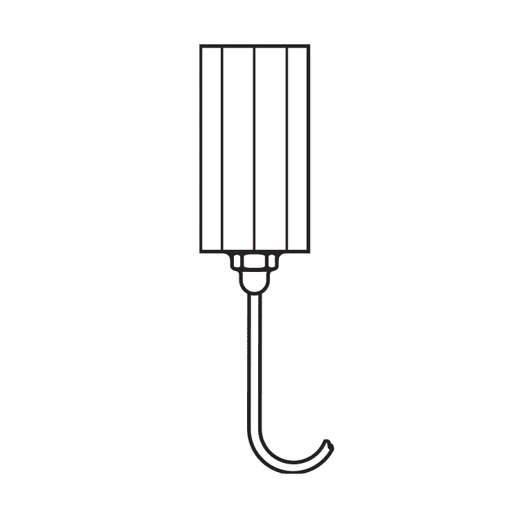
Electric panel heater Solid body type filter on liquid line.
Only available on certain shapes. For more information, contact us!
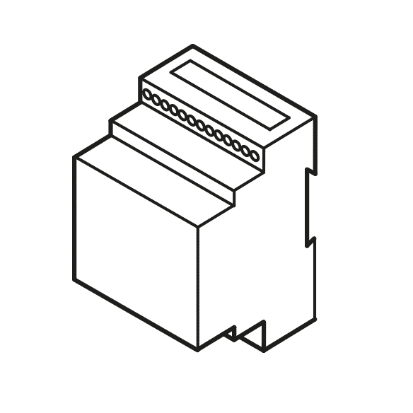
Fan speed regulator Condenser fan speed regulator.
Only available on certain shapes. For more information, contact us!
Different voltage Solenoid valve on the delivery line.
*Only available on certain shapes. For more information, contact us!
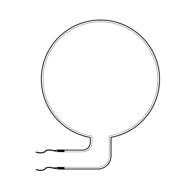
Mouthpiece resistors Resistors around the evaporator fan nozzle.
Available only on certain models. For more information, contact us!
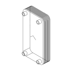
Water condensation Pre-loaded hose and electric cable (connection between condensing and evaporating units) length 10 m.
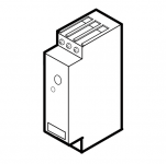
Voltage monitor Pre-loaded hose and electric cable (connection between condensing and evaporating units) length 10 m.
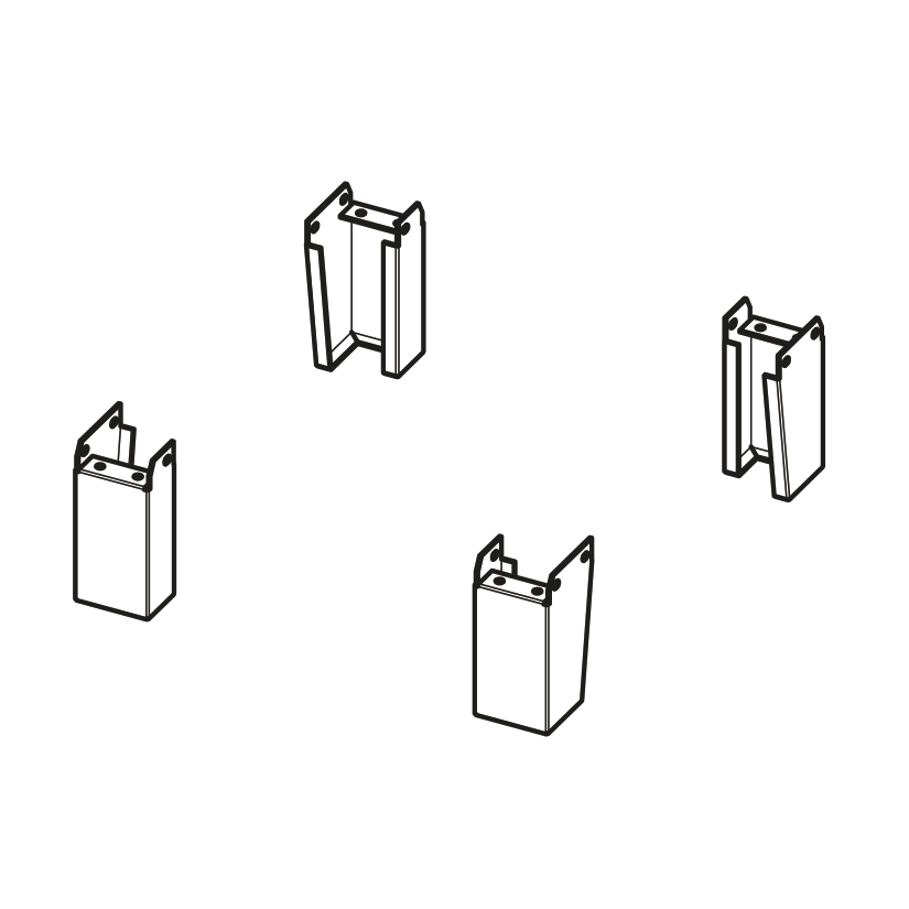
Snow protection Support feet for lifting from the ground.
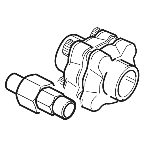
Fittings for connecting OV, BI, UC, UI Fittings for connecting liquid and suction lines for the OV, BI, UC, UI series.
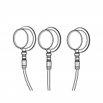
Pressure gauges Electrical box with IP65 protection, fixed next to the finned coil, containing the terminal blocks for connecting fans, resistors, solenoid valve, and temperature probes.
The aforementioned components are completely wired to the relevant terminal blocks.
- Electronic controller with alarm module.
- Expansion type with thermostatic valve.
- All compressors are equipped with crankcase preheating resistor.
- Semi-hermetic compressors are equipped with a thermistor; a differential oil protection pressure switch is installed on models equipped with an oil pump.
- Compressors with displaced volume above 52 m3 /h are part-winding type starting.
- All units are equipped with adjustable low-pressure and high-pressure switches in accordance with the 2014/68/EU “Pressure Equipment” Directive.
- Panel equipped with pressure switches and service outlets accessible while the machine is running.
- Liquid indicator.
- Solenoid valve on the liquid line.
- All models are supplied with liquid receiver with safety valve, in accordance with the Pressure Equipment Directive 2014/68/EU.
- Liquid separator on the suction line.
- Condenser fan control pressure switch. On request, it can be replaced by the electronic variable speed drive of condenser fans.
- Remote control panel including keypad, alarm display, and 5 m long cable already connected to ‘unit (can be supplied on request with different lengths up to 20 meters).
- Direct condensate water discharge.
- Resistance in the condensate drain.
- Installation of ‘condensing unit on the floor outside the cell, installation of ‘evaporator on the ceiling inside the cell.
- Guides for lifting forks in the lower part of the body of condensing units of Forms 3I3-3I5-5I4-5I5-6I4-7I5-8I4-8I5.
- The piping connections between the condensing unit and evaporator are made without welding glands or flanges.
- Resistances around the mouthpiece of evaporator fans in freezing units.
- Weather protection cover

